Hi all. As way of background I am working on a "virtual" preservation site for the Rutland Railroad 6 Mikado locomotive (http://trainperson99.home.comcast.net/~trainperson99). These were USRA standard Light Mikados delivered in 1918. As most of the drawings/pictures of the Rutland's Mikados have been lost, I have widen my search for drawing and information from other lines that also had USRA light Mikados. As deliver, they all followed the USRA specs, so a light Mikado on one railroad was pretty much the same as on another line, manufacture's differences not withstanding. The NYC received a total of 99 light Mikados which it ran on its Cleveland, Cincinnati, Chicago and St. Louis Railway (25), Indiana Harbor Belt Railroad (24), Lake Erie and Western Railroad (15), Michigan Central Railroad (20), and Toledo and Ohio Central Railroad (15) subsidiaries.
I have gotten the CD of drawing for the NYC Class H6/H6a from the NYCHS and they are wonderful (I would highly recommend these to anyone). But as is always the case, the more information you get the more questions you have. Some of this is because of my total lack of knowledge about the mechanics of a steam engine when I started this project. I have since done a lot of reading and I now know enough to know what questions to ask.
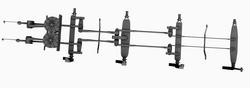
Of late, I have been using the NYCHS drawing to work on the engine's brake rigging. The NYCHS CD had most of the drawings for the individual parts (beam, strap links, equalizers and rod) but no "general drawing" of how the pieces fit together, so using the individual parts and general knowledge I put together the rigging shown below.
click on picture for a full size view.
Ok, now for some questions:
1. In general, does this look correct? The only way I could get it to work is for the link strap in the center of the second beam to be used by both sides. The equalizer is offset, so everything fits but it seem odd that there is only one connection on this beam.
2. How were links-equalizer, rods-equalizer connected. Each had 1 1/4" inside diameter bushing. What did the pin that went through those bushing look like. Was it terminated with a nuts cotter pin?
3. There is a 5/8"x 8 1/2" bolt sticking out the end of each beam. Does anyone know its purpose?
4. Does anyone have any good picture of the driver brake cylinder? I am working off a cutout drawing, but nothing with outside details.
Thanks in advance of any help or assistance and if I am asking my questions in the wrong place, I am sorry, and is there a better place could you point me in the right direction
Jay
I have gotten the CD of drawing for the NYC Class H6/H6a from the NYCHS and they are wonderful (I would highly recommend these to anyone). But as is always the case, the more information you get the more questions you have. Some of this is because of my total lack of knowledge about the mechanics of a steam engine when I started this project. I have since done a lot of reading and I now know enough to know what questions to ask.
Of late, I have been using the NYCHS drawing to work on the engine's brake rigging. The NYCHS CD had most of the drawings for the individual parts (beam, strap links, equalizers and rod) but no "general drawing" of how the pieces fit together, so using the individual parts and general knowledge I put together the rigging shown below.

click on picture for a full size view.
Ok, now for some questions:
1. In general, does this look correct? The only way I could get it to work is for the link strap in the center of the second beam to be used by both sides. The equalizer is offset, so everything fits but it seem odd that there is only one connection on this beam.
2. How were links-equalizer, rods-equalizer connected. Each had 1 1/4" inside diameter bushing. What did the pin that went through those bushing look like. Was it terminated with a nuts cotter pin?
3. There is a 5/8"x 8 1/2" bolt sticking out the end of each beam. Does anyone know its purpose?
4. Does anyone have any good picture of the driver brake cylinder? I am working off a cutout drawing, but nothing with outside details.
Thanks in advance of any help or assistance and if I am asking my questions in the wrong place, I am sorry, and is there a better place could you point me in the right direction
Jay
Home of the virtual USRA Rutland RR Makado http://trainperson99.home.comcast.net