I was recently making drawings of the GE FB-2 truck when I came across a surprising occurrence in some of my photos that I had missed when I first took them.
***
But first, a bit of background:
The brake design on the FB-2 truck is such that when the brakes are applied, the left brake lever becomes more inclined while the right brake lever becomes more vertical. This causes the slack adjuster (running under the truck, connecting the two brake shoes) to slant toward the right slightly as the brakes are applied.
From what I can tell, there were two types of slack adjuster beams used on the FB-2 truck.
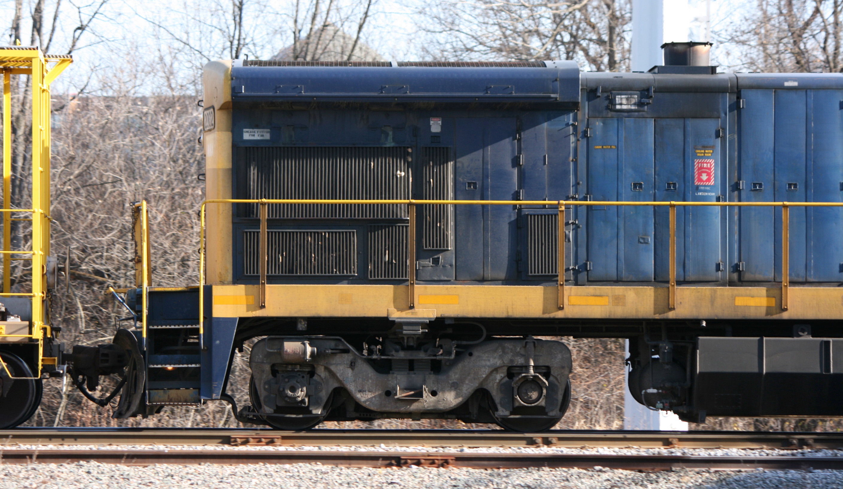
The first was a straight design that tended to be horizontal with the brakes released and slanted with the brakes applied. This is evident in a photo I took of MMA B23-7 2002 (brakes released):
http://trainiax.net/photos/2012/2012-11 ... 20-slr.JPG" onclick="window.open(this.href);return false;
The second was a taller, asymmetrical design that had an angled bracket lowering one side. These tended to be slanted with the brakes released and horizontal with the brakes applied. Shown on MMA B39-8 8553 (brakes released) 8578 (brakes applied):
http://trainiax.net/photos/2005/2005-09 ... 28-mma.JPG" onclick="window.open(this.href);return false;
http://trainiax.net/photos/2006/2006-02 ... 27-mma.JPG" onclick="window.open(this.href);return false;
In both cases, the correct mounting position appears to be with the slack adjuster going over the single brake beam on the left, and inside the double brake beam on the right (visible in as-built photos). In the asymmetrical design, this places the angled bracket with the lowered side at the left.
***
With that out of the way, here are the photos in question - MMA B23-7 2006, sitting in the MMA yard in Sherbrooke, QC on October 31, 2008 (photo 1) and interchange switching on the SLR on April 22, 2013 (photos 2 and 3):
http://trainiax.net/photos/2008/2008-10 ... 31-mma.jpg" onclick="window.open(this.href);return false;
http://trainiax.net/photos/2013/2013-04 ... -04-22.JPG" onclick="window.open(this.href);return false;
http://trainiax.net/photos/2013/2013-04 ... -04-22.JPG" onclick="window.open(this.href);return false;
First observation: Between these photos, the right front slack adjuster beam was changed from the straight design to the asymmetrical design. The truck itself (Adirondack casting with a knuckle bracket) was the same.
Second observation: The replaced slack adjuster was mounted the reverse of what I have seen on most other units, with the angled bracket at the right. This means that a) it slants sharply to the right with the brakes applied; and b) it does not apply a symmetrical load to the brake levers or pins, since the normal inside-outside lever connections are reversed (resulting in three mounting surfaces on the right and one on the left.)
Third observation: The slack adjuster itself was broken or otherwise not functional, meaning that with the brakes applied (brake cylinder piston extended) the brake shoes were making no contact with the wheels.
Fourth observation: As this was the front right corner of the locomotive, under these circumstances this locomotive did not have a functioning handbrake.
I don't know if it was merely a coincidence - perhaps I happened upon the unit right after the slack adjuster had broken - but it was quite a startling find.
***
But first, a bit of background:
The brake design on the FB-2 truck is such that when the brakes are applied, the left brake lever becomes more inclined while the right brake lever becomes more vertical. This causes the slack adjuster (running under the truck, connecting the two brake shoes) to slant toward the right slightly as the brakes are applied.
From what I can tell, there were two types of slack adjuster beams used on the FB-2 truck.
The first was a straight design that tended to be horizontal with the brakes released and slanted with the brakes applied. This is evident in a photo I took of MMA B23-7 2002 (brakes released):
http://trainiax.net/photos/2012/2012-11 ... 20-slr.JPG" onclick="window.open(this.href);return false;
The second was a taller, asymmetrical design that had an angled bracket lowering one side. These tended to be slanted with the brakes released and horizontal with the brakes applied. Shown on MMA B39-8 8553 (brakes released) 8578 (brakes applied):
http://trainiax.net/photos/2005/2005-09 ... 28-mma.JPG" onclick="window.open(this.href);return false;
http://trainiax.net/photos/2006/2006-02 ... 27-mma.JPG" onclick="window.open(this.href);return false;
In both cases, the correct mounting position appears to be with the slack adjuster going over the single brake beam on the left, and inside the double brake beam on the right (visible in as-built photos). In the asymmetrical design, this places the angled bracket with the lowered side at the left.
***
With that out of the way, here are the photos in question - MMA B23-7 2006, sitting in the MMA yard in Sherbrooke, QC on October 31, 2008 (photo 1) and interchange switching on the SLR on April 22, 2013 (photos 2 and 3):
http://trainiax.net/photos/2008/2008-10 ... 31-mma.jpg" onclick="window.open(this.href);return false;
http://trainiax.net/photos/2013/2013-04 ... -04-22.JPG" onclick="window.open(this.href);return false;
http://trainiax.net/photos/2013/2013-04 ... -04-22.JPG" onclick="window.open(this.href);return false;
First observation: Between these photos, the right front slack adjuster beam was changed from the straight design to the asymmetrical design. The truck itself (Adirondack casting with a knuckle bracket) was the same.
Second observation: The replaced slack adjuster was mounted the reverse of what I have seen on most other units, with the angled bracket at the right. This means that a) it slants sharply to the right with the brakes applied; and b) it does not apply a symmetrical load to the brake levers or pins, since the normal inside-outside lever connections are reversed (resulting in three mounting surfaces on the right and one on the left.)
Third observation: The slack adjuster itself was broken or otherwise not functional, meaning that with the brakes applied (brake cylinder piston extended) the brake shoes were making no contact with the wheels.
Fourth observation: As this was the front right corner of the locomotive, under these circumstances this locomotive did not have a functioning handbrake.
I don't know if it was merely a coincidence - perhaps I happened upon the unit right after the slack adjuster had broken - but it was quite a startling find.
--Michael Eby
--http://trainiax.net
--http://trainiax.net