Railroad Forums 

  • Fireman's task - with 23 042 up to Gerolstein

  • Discussion of steam locomotives from all manufacturers and railroads
Discussion of steam locomotives from all manufacturers and railroads

Moderators: Typewriters, slide rules

 #794059  by Steffen
 
Hello,
there are so many nice threads, but I miss a theme, were we can post our videos or pictures.
So I want to start this with my self-made video from my task on the german passenger locomotive, series 23.
It's suburban/urban traffic railroad engine, designed for mid range distances with many stops on various stations and the ability to return without getting turned on a turn-table nearly that fast as heading forward. It's 2-6-2 axle set makes it able to go forward and backward nearly same speed, because having a new tender design, which has favourable leading abilities to support the reverse motion action better than common tenders.
I was planned to replace the prussian P8, a 4-6-0 passenger engine, but the change in traction from steam to diesel and electric did not lead to further development or improvement of series 23 light passenger engines.
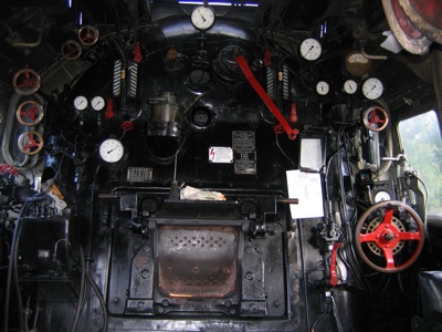
So our engine got a Henschel high performance boiler, but did not get the Henschel direct feedwater heater and the modern SKF rod roller bearings...

Around easter, we encounter a large steam action festival, called Plandampf or steam spectacle. Regular service traines were replaced with steam trains or historical diesel or electirc trains. So our 23 had to take one trains in the morning task and one trains in the afternoon task, each train from Trier to Gerolstein and return.
The rgular modern diesel railcar was replaced by our steam train, but the shedule was the same as for the 50 years younger railcars, so we had to compete, historical vs. modern.
What should I tell you? The 1954 build Henschel series 23 made the task! Four days, whitout any delay, and usually more load, that the modern trains had so service, because we had lot's of spectators in the train, who to the chance, to go historical for the same price as with the diesel railcars each days...
From Trier to Gerolstein the line is even, but after Ehrang the track splits and the climb along the brook Kyll up to Gerolstein starts. From here the fireman has to do a lot, because the shedule is made for 43 up to 49 mph uphills, the the engine won't hold any power back, because to stay in shedule, he has to take the engines power well. It needs to speed up the train fast, to get on the need travel speed, as well as many tunnels need the fireman to be just in time with the fire, to ensure a good fire, because firing in tunnel is forbidden.

So I made this Video, hope you enjoy how the task was done.
It's made with a Contour helmet cam, so it's PoV, and I guess: See and feel like the fireman...

http://www.youtube.com/watch?v=HcDim_0Dro
 #795409  by Steffen
 
Okay, guess to show up a little more.
Sorry, but I had not the right picture at hand, but:
Cabs for most german locomotives are more or less uniform in design, so we can take another cab, to see what's controlling what...
Image

This is the cab of a german pacific, series 01. The 01 Series was the leading express engine in the "Deutsche Reichsbahn Gesellschaft" from 1920 to 1937, and even later within the "Deutsche Reichsbahn" of the German Democratic Republic and the "Deutsche BundesBahn" of the Federal Republic of Germany.
Also during the black times of Germany, the 01 was still leading and most valuable express locomotive in service.
Having about 2200 hp and a boiler pressure of 232 psi it was able to travel with a maximum allowed speed of 80 mph.
Because of many parts being uniform and exchange able with other locomotives, in example the boiler and cylinders with the series 44 heavy freight locomotive, the germans speak of the Uniform-locomotives type.
This type replaced the former locomotives, which were build by the country railroads of the federal states in Germany, like the Prussian or Bavarian state Railroad. So many valuable federal state railroad locomotives were planed to be replaced by a new uniform type, but after WW2 many federal state railroad locomotives still survived till the end of steam in germany, like the prussian P8, for example.
In the video you will see the end of steam development, with a backdraws and historical fripperies which made steam never a match to new coming diesels, this is the uniform type locomotive series 23, which was planned as replacement fpr the prussian P8, but because of many misconstructions and misleadings in management of construction and service, the engine never replaced the prussian P8 as desired or planned.

Back to the picture: Uniform locomotives have nearly same cabs, so most handwheels for valve control are placed on the comparable places in the cab, just to ensure, that a fireman orientates well within the different locomotive types.
So the series 01 cab is larger, has more space because of the bigger boiler and the rear open cab, but the handwheel arrangement is compareable within the series 23 in the video.

So, let's start at the left side, the firemans side. The big black box and the left bottom is the main oil feed pump, which is driven by coupler from the connecting rod, and feeds oil to the cylinders and piston valves.
Above is placed, difficult to see, a three cock valve, which delivers extinction water to coal tender, ashpan and smoke box, just to ensure the extinct any glowing ashes or clinkers, and even prevent coal from being to dusty or get to self-ignitation of coal in the tender in hot summers.
Not visible is the handle for the main feed injector, the spindle for the grate pit and the control handle for the pneumatic boiler blow-down valve.
Good visible are the handwheels for the valves of: From bottom to top: blower, march boiler feed pump and electric generator.
The blower is the most important valve for the fireman, because if the engine is not working, because in idle downhill or standing at a stop or station, the blower supplies steam to the exjector exhaust of the chimney, so supports the boiler with a extra draught or air through the fire and the boiler smoke tubes, and helps to prevent backdrafts of fire through the open firedoor into the cab.
The march pump is a large piston water pump. I do not have any clue or guess what in america was used, as I miss books and informations on this technical topics, but here a Knorr tandem feedwater pump with Tolkin control was used (if you wish, I can report more details on the german feed water pumps). This pump draw the water from the tender and feed it to the main feedwater heater. It was a Knorr surface heater, a large drum with a heat exchange convector inside, a so called non-contact or indirect heater, and from there thru the top-clacs into the boiler.
Because of being only filled with exhaust steam, the Knorr heater only heated the feedwater during the run of the engine with open throttle, it was called march pump or drive pump. Because if the engine was not moving under steam, the heating of feedwater wasn't good or inferior, so the pump only has to be used when the engine was running with open throttle. For all other circumstances, the injector had to be used.
The electric generator is a small single-level steam turbine, connected to a 24 Volt DC Generator for illumination and electromagnetic train safty controls.
The large gauge on the 01 cab left is the temperature gauge for the feedwater pump, if was abandoned on later series of the uniform locomotive types.
The small gauges left are the feedwater stroke gauge and the steam heating control gauge.
The valve for steam heating for the coaches was one of the smaller handwheels left side atop of the boiler rear end.
The water gauges are easy to recognized and need no further description. Mid atop of the boilers rear end is the main pressure gauge located, visible for driver and fireman.
At the right side, the drivers side we locate the main spindle of the valve gear control, left the pneumatic control for the cylinder drain cocks (most uniform type locomotives had not pneumatic controls, a lever close to the valve gear spindle controlled the cylinder drain cocks mechanically). The handwheel above the large wheel of the gear controls if the valve control of the air compressor for the Knorr air brakes of engine and train. The brake controlls are the two small, not easy to see, levers at the widow above the valve gear control.
Beyond the valve gear wheel the tachometer is visible and above the valve control of the compressor the three brake gauges are located, showing pressure in main air reservoir, main air line and pressure in air brake cylinders.
The dull grey gauge above the three brake gauges is the temperature meter for superheater, which is while engine working hardly more than 660° F
The last, large gauge on the drivers side is the pressure control of steam pressure in the piston inlet, which shows how strongly the engine is hanging on the boiler pressure.
The main, nearly mid placed lever is the steam throttle, the main steam output control of the boiler, here a Wagner satured steam main valve.

Below he firedoor, not visible in the picture are the levers for the front and rear air flaps, or air inlet dampers and on the driver side the control of the ash pan or ash box doors, to remove ash and clinkers on the ash pit in the shop/home shed.
 #795743  by Cactus Jack
 
Excellent, now it is easier to understand what I am looking at.

As for your comment: The last, large gauge on the drivers side is the pressure control of steam pressure in the piston inlet, which shows how strongly the engine is hanging on the boiler pressure.

What is the delta or differential to be expected between the piston inlet and boiler pressure ?
 #795854  by Steffen
 
Jack,
a flow allways exist only, if a delta is present. So if the boiler has 232 psi, you never will have the same in the piston valve inlet.
So the given delta is about 3 up to 10 psi, depending on locomotive design and internal streamline of the steam tubes and flow.
So I have seen hard working freight engines with the needle at top pressure and 232 psi in steam inlet. To be honest: The boiler would then have around 234 or 235 psi and the inlet would be at 230 or 231 psi, so only little difference, but enough to set up a continuos flow.
Visible is this not realy at the gauges, but you can hear:
If the engine runs hard working, and the fireman does the task well, the safeties won't lift, even at the somewhat higher pressure than normal, but: There is enough volume of steam consumptioned by the engine, so there to less volume to push open the safety valves... but now: The driver closes the throttle... and now guess what happens first!!!

Yes, the safeties will open immediately, because you won't be able to bring in that mass of water to reduce the volume build up in the boiler and prevent the safeties from opening.... no way. So the safeties lift and get loud, even with the pumps going at full power... that's a hearable sign of engines a couple of minutes before going on the edge at maximum boiler output capacity...
 #796976  by Steffen
 
Well, Jack,
if you can tell me when to come, maybe I can give you some tips, were to go :)
Consider german engines as smaller than main line US steamers, because there is a significant difference in the range had to be traveled without turning and taking water and coal. In Germany this was usually less than 250 miles, so the range of a mainline express engine can assumed to be about 125 miles, after this it was changed to another engine, or it has to be take water and maybe get some coal...
So there was no need for such huge monsters, like a Niagara type locomotive ;)