This thread stems from the recent postings on page 3 of the thread “Serial Curiosity” in the General Electric forum (viewtopic.php?f=8&t=159725&start=30" onclick="window.open(this.href);return false;), which had digressed into a discussion of GE B-B-B-B locomotives and then into EMD’s developments in that field. It seemed appropriate to divert into the General Discussion forum.
Finding a suitable title for this thread was not so easy. Initially I was thinking of “Four-Truck Locomotives”, which would have covered the primary target of the B-B-B-B types, but would have left out the EMD D-D types, which nevertheless are part of the story. “Eight Axle, Eight Motor Locomotives” looked good until I saw that it excluded an unusual design that otherwise justifies inclusion here. “Eight Axle Locomotives” allows in a diversity of wheel arrangements, but the number is nevertheless manageable.
Anyway, looking first at diesel and gas-turbine locomotives with eight powered axles and either two or four trucks, the sequence of nodal points in respect of running gear layout appears to be:
1. 1936: EMC T; B-B+B-B with articulated span bolsters
2. 1949: GE GTEL4500, B-B-B-B with couplers on span bolsters
3. 1950: Westinghouse GTEL: B-B-B-B with independent trucks.
4. 1963: GE U50; B-B-B-B with couplers on span bolsters
5. 1963: EMD DD35; D-D (with following models DD35A and DDA40X)
6. 1964: Alco C855A,B; B-B-B-B with couplers on span bolsters
7. 1969: CEM BB-BB; B-B-B-B with span bolsters and monomoteur trucks; Cape/metre gauge
8. 1970: EMD DDM45; D-D metre gauge
9. 1991: GE BB40-8; B-B-B-B with span bolsters; metre gauge (with following models)
10. 2015: EMD SD70ACe-BB; Low-profile B-B-B-B with span bolsters; metre gauge
The EMC T was a “one-off”, and followed established practice for electric locomotives, in which the span bolsters carried all buff and drag forces from one coupler through their articulated connection to the other coupler, with the locomotive body “floating” on the two span bolsters. Each span bolster rode upon two independent B trucks. Kirkland quoted the Illinois Terminal and Oregon Electric B-B+B-B electric locomotives as antecedents for the wheel arrangement used for the EMC T, and indeed these had the articulated span-bolster form. Judging by the photographic evidence, the Illinois Terminal locomotives at interest had swing-bolster trucks, and the Oregon Electric locomotives might have had. But the EMC T looks to have had rigid-bolster trucks. Presumably its expected operating speeds were low enough that such were acceptable. Kirkland also quoted the NYC T class electrics dating from 1913 as an even earlier antecedent. But these were different, in that they did not have span bolsters as such, but were arranged with the outer trucks as pilots to the inners, whose frames were extended outwards accordingly. They could be thought of as being of the 2-B+B-2 form modified by fitting traction motors to the outer trucks. The use of pilot trucks offset the unfavourable lateral tracking qualities of the articulated truck arrangement and so enabled higher speeds than could be achieved with a B+B arrangement for a given maximum lateral railhead force. The same would be true of the NYC version of the B-B+B-B wheel arrangement. NYC also positioned the outer trucks well outboard, which likely would have helped with lateral tracking and riding.
Within the NYC T class, there appear to have been two forms of outer truck mounting. One might be described as “normal”, with the truck pivot at its centre and with what I assume was provision for lateral motion, although the latter is unconfirmed. The other was with long radius bars, pivoted to the main truck frames just outside of the inner axle pairs, and which probably handled all buff and drag forces for their respective outer trucks. Thus the outer truck mountings would have been for loading and lateral control only. Why the difference and which came first I don’t know. I’d lean towards the “normal” arrangement as being better at higher speeds, but maybe it wasn’t so. Be that as it may, the NYC T four-truck arrangement appears not to been repeated in either form.
After WWII, GE appeared to adopt a “horses-for-courses” approach. The Virginian EL2B motor-generator electric locomotives were of the articulated span-bolster B-B+B-B form, with rigid-bolster trucks. Evidently the resultant tracking qualities must have been seen as adequate for the moderate speeds at which these locomotives operated, and the articulation of the span bolsters, with joints that look to have been single-axis with but minimal pitch axis freedom, would have helped minimize inter-span bolster and inter-truck weight transfer. These may have been the only “big”, Class I road electric locomotives to have had articulated span-bolster running gear though, as the earlier examples quoted were for terminal and interurban roads.
But for the GTEL4500, articulation of the span bolsters was abandoned. In part this allowed for the mounting of underslung equipment between the trucks, but it was also preferable for higher speed running, in that each span-bolster could oscillate at its own frequency and amplitude without being interfered with by the other. Also, the trucks were of the regular swing-bolster type. Each truck was of course independent, transmitting its local buff and drag forces to its associated span bolster by its centre pivot. GE chose to mount the couplers on the span bolsters rather than on the locomotive frame. This may have been to minimize coupler offset on tight curves, and perhaps it was also a carryover from articulated span-bolster practice. This in turn meant that the pathway for buff and drag forces was from coupler via the span bolster to the span-bolster pivot, thence via the locomotive frame to the other span-bolster pivot and through the span bolster to the other coupler. As a result the span bolsters had heavier construction for their outboard sections.
Westinghouse chose a simpler arrangement for its gas-turbine prototype. Each of the four trucks was directly connected to the locomotive frame. Lateral motion for each was provided by a roller frame upon which the locomotive body was mounted, although how secondary springing was provided was not described in anything that I have seen. Lateral movement of the outer trucks was spring-controlled, whereas the inner trucks were free. Thus the outer trucks did the guiding around curves, and perhaps this also made it possible to mount the couplers on the locomotive frame, as the effective pivot points were not far from the frame outer ends. One imagines that this approach to the B-B-B-B wheel arrangement would not have allowed easy traversing of other than minor track vertical curvature, but given that it was geared for 100 mile/h running, Westinghouse evidently had high-speed passenger service in mind, where significant vertical curves were unlikely to be encountered, at least whilst hauling trains.
This four-truck layout was not repeated, but the roller platform made a reappearance in Japanese B-B-B locomotive practice in the 1960s, being used for centre trucks where free and significant lateral movement was required, and where previously special link mechanisms had been used.
In the 1960s, GE and Alco repeated the GTEL4500 layout for their respective U50 and C855 models, whereas EMD adopted D-D trucks for its DD35. These gained simplicity at the expense of a long rigid wheelbase. And EMD repeated the D-D wheel arrangement for the metre-gauge DDM45 supplied to Brasil from 1970; anecdotal evidence at least suggests that the ling rigid wheelbase was not ideal in that application.
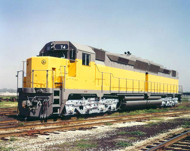
Meanwhile the French company CEM had developed an eight-axle export design with African applications in mind, which it referred to as a BB-BB type. This was a double end-cab unit that had a single powerplant for 3600 hp with weights from around 265 000 lb upwards. It had a B-B-B-B wheel arrangement with independent span bolsters and couplers mounted on the locomotive main frame. Characteristic of French practice of the period, it had “monomoteur” trucks, that is with one large traction motor (8-pole, compensated) driving a pair of axles. So it was technically a four-motor locomotive. Possibly because the monomoteur arrangement would have made provision of individual truck lateral motion difficult, it was the span bolster that had swing-link type lateral motion. A fleet was built for Congo Ocean (Cape gauge) and one for Madagascar (metre gauge). I think that in practice it proved to be too big. The sub-Saharan roads at least seemed to prefer more conventional locomotives of around 2000 hp. For example, The GE U20C was very popular, and could be thought of as a quintessentially African locomotive. Concurrently with the BB-BB model, CEM also offered a homologous conventional B-B design. It also built a solitary B-BB example, which had a single B truck at one end and a B-B span-bolster truck at the other end. That was surely an ersatz way of doing a B-B-B wheel arrangement.
Forward to 1991, GE introduced its metre gauge BB40-8 for service in Brasil. This was of the span-bolster type, with the couplers mounted on the locomotive main frame, so in respect of the latter feature, it was a departure for GE. That same basic form, although quite different in detail, was adopted last year by EMD for its SD70ACe-BB.
And now the B-B-B-B type is back in Africa, in Mozambique to be exact, in the form of the GE BB40-9WM.
For the record, here are some other eight-axle wheel arrangements used for electric and diesel locomotives are:
2-D-2: Electric and diesel-electric; built until the mid-1950s.
1A-D-A1: Diesel-electric; one build late 1940s.
2-B+B-2 Electric; all pre-WWII as far as I know.
1-C+C-1 Electric, probably more in Japan than anywhere else, built to about 1958.
1-C-C-1 Diesel-electric; 732 worldwide from 1951 through circa1978.
Truck design ranging from “couldn’t be worse (although it actually was” to
“excellent”.
C+B+C Diesel-electric; 1950 through 1956
C-2-C: Diesel-electric; one build 1953-54.
GE probably wins the prize for building (or at least equipping) the biggest variety of eight-axle locomotives. Its list includes: B-B+B-B (in two sub-variants); B-B-B-B (in two subvariants); 2-D-2; 2-B+B-2; 1-C+C-1; 1-C-C-1; C+B+C; and C-2-C. As best I can determine, it was the only builder of the C+B+C and C-2-C types.
Cheers,
Finding a suitable title for this thread was not so easy. Initially I was thinking of “Four-Truck Locomotives”, which would have covered the primary target of the B-B-B-B types, but would have left out the EMD D-D types, which nevertheless are part of the story. “Eight Axle, Eight Motor Locomotives” looked good until I saw that it excluded an unusual design that otherwise justifies inclusion here. “Eight Axle Locomotives” allows in a diversity of wheel arrangements, but the number is nevertheless manageable.
Anyway, looking first at diesel and gas-turbine locomotives with eight powered axles and either two or four trucks, the sequence of nodal points in respect of running gear layout appears to be:
1. 1936: EMC T; B-B+B-B with articulated span bolsters
2. 1949: GE GTEL4500, B-B-B-B with couplers on span bolsters
3. 1950: Westinghouse GTEL: B-B-B-B with independent trucks.
4. 1963: GE U50; B-B-B-B with couplers on span bolsters
5. 1963: EMD DD35; D-D (with following models DD35A and DDA40X)
6. 1964: Alco C855A,B; B-B-B-B with couplers on span bolsters
7. 1969: CEM BB-BB; B-B-B-B with span bolsters and monomoteur trucks; Cape/metre gauge
8. 1970: EMD DDM45; D-D metre gauge
9. 1991: GE BB40-8; B-B-B-B with span bolsters; metre gauge (with following models)
10. 2015: EMD SD70ACe-BB; Low-profile B-B-B-B with span bolsters; metre gauge
The EMC T was a “one-off”, and followed established practice for electric locomotives, in which the span bolsters carried all buff and drag forces from one coupler through their articulated connection to the other coupler, with the locomotive body “floating” on the two span bolsters. Each span bolster rode upon two independent B trucks. Kirkland quoted the Illinois Terminal and Oregon Electric B-B+B-B electric locomotives as antecedents for the wheel arrangement used for the EMC T, and indeed these had the articulated span-bolster form. Judging by the photographic evidence, the Illinois Terminal locomotives at interest had swing-bolster trucks, and the Oregon Electric locomotives might have had. But the EMC T looks to have had rigid-bolster trucks. Presumably its expected operating speeds were low enough that such were acceptable. Kirkland also quoted the NYC T class electrics dating from 1913 as an even earlier antecedent. But these were different, in that they did not have span bolsters as such, but were arranged with the outer trucks as pilots to the inners, whose frames were extended outwards accordingly. They could be thought of as being of the 2-B+B-2 form modified by fitting traction motors to the outer trucks. The use of pilot trucks offset the unfavourable lateral tracking qualities of the articulated truck arrangement and so enabled higher speeds than could be achieved with a B+B arrangement for a given maximum lateral railhead force. The same would be true of the NYC version of the B-B+B-B wheel arrangement. NYC also positioned the outer trucks well outboard, which likely would have helped with lateral tracking and riding.
Within the NYC T class, there appear to have been two forms of outer truck mounting. One might be described as “normal”, with the truck pivot at its centre and with what I assume was provision for lateral motion, although the latter is unconfirmed. The other was with long radius bars, pivoted to the main truck frames just outside of the inner axle pairs, and which probably handled all buff and drag forces for their respective outer trucks. Thus the outer truck mountings would have been for loading and lateral control only. Why the difference and which came first I don’t know. I’d lean towards the “normal” arrangement as being better at higher speeds, but maybe it wasn’t so. Be that as it may, the NYC T four-truck arrangement appears not to been repeated in either form.
After WWII, GE appeared to adopt a “horses-for-courses” approach. The Virginian EL2B motor-generator electric locomotives were of the articulated span-bolster B-B+B-B form, with rigid-bolster trucks. Evidently the resultant tracking qualities must have been seen as adequate for the moderate speeds at which these locomotives operated, and the articulation of the span bolsters, with joints that look to have been single-axis with but minimal pitch axis freedom, would have helped minimize inter-span bolster and inter-truck weight transfer. These may have been the only “big”, Class I road electric locomotives to have had articulated span-bolster running gear though, as the earlier examples quoted were for terminal and interurban roads.
But for the GTEL4500, articulation of the span bolsters was abandoned. In part this allowed for the mounting of underslung equipment between the trucks, but it was also preferable for higher speed running, in that each span-bolster could oscillate at its own frequency and amplitude without being interfered with by the other. Also, the trucks were of the regular swing-bolster type. Each truck was of course independent, transmitting its local buff and drag forces to its associated span bolster by its centre pivot. GE chose to mount the couplers on the span bolsters rather than on the locomotive frame. This may have been to minimize coupler offset on tight curves, and perhaps it was also a carryover from articulated span-bolster practice. This in turn meant that the pathway for buff and drag forces was from coupler via the span bolster to the span-bolster pivot, thence via the locomotive frame to the other span-bolster pivot and through the span bolster to the other coupler. As a result the span bolsters had heavier construction for their outboard sections.
Westinghouse chose a simpler arrangement for its gas-turbine prototype. Each of the four trucks was directly connected to the locomotive frame. Lateral motion for each was provided by a roller frame upon which the locomotive body was mounted, although how secondary springing was provided was not described in anything that I have seen. Lateral movement of the outer trucks was spring-controlled, whereas the inner trucks were free. Thus the outer trucks did the guiding around curves, and perhaps this also made it possible to mount the couplers on the locomotive frame, as the effective pivot points were not far from the frame outer ends. One imagines that this approach to the B-B-B-B wheel arrangement would not have allowed easy traversing of other than minor track vertical curvature, but given that it was geared for 100 mile/h running, Westinghouse evidently had high-speed passenger service in mind, where significant vertical curves were unlikely to be encountered, at least whilst hauling trains.
This four-truck layout was not repeated, but the roller platform made a reappearance in Japanese B-B-B locomotive practice in the 1960s, being used for centre trucks where free and significant lateral movement was required, and where previously special link mechanisms had been used.
In the 1960s, GE and Alco repeated the GTEL4500 layout for their respective U50 and C855 models, whereas EMD adopted D-D trucks for its DD35. These gained simplicity at the expense of a long rigid wheelbase. And EMD repeated the D-D wheel arrangement for the metre-gauge DDM45 supplied to Brasil from 1970; anecdotal evidence at least suggests that the ling rigid wheelbase was not ideal in that application.
Meanwhile the French company CEM had developed an eight-axle export design with African applications in mind, which it referred to as a BB-BB type. This was a double end-cab unit that had a single powerplant for 3600 hp with weights from around 265 000 lb upwards. It had a B-B-B-B wheel arrangement with independent span bolsters and couplers mounted on the locomotive main frame. Characteristic of French practice of the period, it had “monomoteur” trucks, that is with one large traction motor (8-pole, compensated) driving a pair of axles. So it was technically a four-motor locomotive. Possibly because the monomoteur arrangement would have made provision of individual truck lateral motion difficult, it was the span bolster that had swing-link type lateral motion. A fleet was built for Congo Ocean (Cape gauge) and one for Madagascar (metre gauge). I think that in practice it proved to be too big. The sub-Saharan roads at least seemed to prefer more conventional locomotives of around 2000 hp. For example, The GE U20C was very popular, and could be thought of as a quintessentially African locomotive. Concurrently with the BB-BB model, CEM also offered a homologous conventional B-B design. It also built a solitary B-BB example, which had a single B truck at one end and a B-B span-bolster truck at the other end. That was surely an ersatz way of doing a B-B-B wheel arrangement.
Forward to 1991, GE introduced its metre gauge BB40-8 for service in Brasil. This was of the span-bolster type, with the couplers mounted on the locomotive main frame, so in respect of the latter feature, it was a departure for GE. That same basic form, although quite different in detail, was adopted last year by EMD for its SD70ACe-BB.
And now the B-B-B-B type is back in Africa, in Mozambique to be exact, in the form of the GE BB40-9WM.
For the record, here are some other eight-axle wheel arrangements used for electric and diesel locomotives are:
2-D-2: Electric and diesel-electric; built until the mid-1950s.
1A-D-A1: Diesel-electric; one build late 1940s.
2-B+B-2 Electric; all pre-WWII as far as I know.
1-C+C-1 Electric, probably more in Japan than anywhere else, built to about 1958.
1-C-C-1 Diesel-electric; 732 worldwide from 1951 through circa1978.
Truck design ranging from “couldn’t be worse (although it actually was” to
“excellent”.
C+B+C Diesel-electric; 1950 through 1956
C-2-C: Diesel-electric; one build 1953-54.
GE probably wins the prize for building (or at least equipping) the biggest variety of eight-axle locomotives. Its list includes: B-B+B-B (in two sub-variants); B-B-B-B (in two subvariants); 2-D-2; 2-B+B-2; 1-C+C-1; 1-C-C-1; C+B+C; and C-2-C. As best I can determine, it was the only builder of the C+B+C and C-2-C types.
Cheers,