Railroad Forums 

  • "FA-2/4"

  • Discussion of products from the American Locomotive Company. A web site with current Alco 251 information can be found here: Fairbanks-Morse/Alco 251.
Discussion of products from the American Locomotive Company. A web site with current Alco 251 information can be found here: Fairbanks-Morse/Alco 251.

Moderator: Alcoman

 #1492894  by Allen Hazen
 
Title is meant to suggest hybrids or intermediates or ...
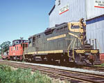
I believe that, when the 12-251 engine was new but before it was introduced on production locomotives, a small number of FA-2 locomotives (Lehigh Valley? and/or New York Central?) were (temporarily?) re-engined with 251 engines for testing.
QUESTIONS: (1) General information about the test program and the locomotives involved? (Open-ended question!)
(2). I think the dimensions of the 12-251 and 12-244 engines were slightly different. (2a) How different? And that, though there was enough room inside the FA-2 carbody to allow the slightly larger engine to be fitted in, this might not have been possible with an FA-1. (2b) Is this so?
--
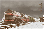
In addition to its new-build FPA-4 locomotives, Canadian National had a small number (2?) of FP-2 locomotives that had been re-built with 251 engines. I think they were rebuilt slightly before the FPA-4 units were build; I assume that their success was what convinced CN to order the FPA-4.
QUESTIONS: (3) Relevant historical details on this episode?
(4) Were the rebuilt FPA-2 and the new-build FPA-4 treated as equivalent by CN?
(5) Slightly more general: Other than having the newer, slightly more powerful, engine (and the external aftercooler radiator that reveals it), how different was an FPA-4 from an FPA-2? Was the carbody structure (framing, truss spacing, etc) the same?
 #1492937  by tgibson
 
From this site:

http://cs.trains.com/mrr/f/13/t/129589.aspx" onclick="window.open(this.href);return false;

The lengths are stated as:

Length FA-1 51' 6"

Length FB-1 50' 2"

Length FA-2 53' 6"

Length FB-2 52' 8"

Length FPA-4 54' 0"

Length FPB-4 53' 2"

But the CN diagrams say they were the same length, so I don't know. That data and many of the details of the conversions can be found here:

https://www.exporail.org/can_rail/Canad ... 2_1967.pdf" onclick="window.open(this.href);return false;

Hope this helps,
 #1492940  by scottychaos
 
Two Lehigh Valley units.
594 was a FA2.
583 was a FB2.

"In 1955, FA/Bs Nos. 583 and 594 returned to Schenectady where they underwent several major mechanical changes, chief among the many upgrades was the installation of a new 1800-horsepower V-12 251 engine. For nearly a year the pair of prototype "FA-3s" served as rolling test beds and enabled Alco product development engineers to assess the new power plant's performance and rediness to replace the 244 engine. Alco re-installed the V12 244 prime movers in the two carbodies, which remained on the roster for another seven years."

from:
https://scotlawrence.github.io/LValltimeroster/" onclick="window.open(this.href);return false;

Scot
 #1493023  by Allen Hazen
 
Scott, Tom--
Thanks for your replies! It will take a while to digest all the information in the links you provide: if I have intelligent comments to make, I'll post them.
One odd thing I noticed. The first of the FPA-2 re-engined with 281 was "released" a few days AFTER the build date for the first FPA-4. So experience with the re-builds obviously didn't contribute to the decision to order the FPA-4: the re-engine and new-build programs were simultaneous. Leaving the question: why were two, but only two, of the FPA-2 re-engined? (Maybe somebody decided, after the first new and the first upgraded units were in service (but not long after!) that there wasn't enough of an improvement to make it worth spending the money to re-engine the rest of the FPA-2 fleet?)
--
The possible six-inch length difference is puzzling. At a guess, if it is real, it might be a matter of different couple shanks or draw-gear, with the same car-body length. Or maybe the shorter length is that of Schenectady-built FA/FPA-2, with MLW building theirs just a bit longer?
--
Thanks again!
 #1493024  by Allen Hazen
 
Hmm...
I compared the FA-2 drawings from the New York Central and the Pennsylvania (both online at George Elwood's marvellous "Fallen Flags" rail image site. They agree with the CN diagrams that the truck centre spacing is 29'2", but have the ends each three inches shorter: 12'7" to the front coupler and 11'7" to the rear coupler from the respective truck centres, where the CN diagram gives 12'10 inches and 12'0".

I think the conventional "length" to give for a diesel locomotive is the length between the coupler pulling faces, the "coupled length". At least one of the diagrams explicitly noted that this was what was meant, and the placement of the vertical lines at the ends of the length bars suggest that this is what all the diagram drawers intended. So apparently CN's FPA-2/FPA-4 were a bit longer than the U.S.-built versions.
 #1493138  by jr
 
Allen,

The NY&LE has an operating(?) copy of each of the upgraded (CN) FPA2 and FPA4.

http://www.rrpicturearchives.net/showPi ... id=1777961

Photo attached provides some external spotting information. Perhaps they might have some further details on internals, measurements, etc.?


JR
 #1493433  by mp15ac
 
I might be wrong, but I believe that CN re-engined four FPA-3 with 251 engines, and then used the four 244 engines in the four RSC-24 units.

Stuart
 #1493444  by Allen Hazen
 
Stuart--
You're right. I have been sloppily talking about "FPA" units without distinguishing the "FPB" B-units. CN had two FPA-2 and two FPB-2 units re-engined, and, yes, the spare 12-244 engines (de-rated to 1400 hp) were used on the lightweight RSC-24 road switchers. (Alco gave a 1400 hp rating to the "250" engines -- rebuilt and modernized 244 engines -- that they installed in a number of factory rebuilds of early FA and RS types in the late 1950s?/early 1960s?)
--
On the length mystery. I checked Kirkland's Alco book ("The Diesel Builders, volume 2"). He gives the shorter lengths for the original FA-2 and FB-2, and says that the six-inch increase in length was made with the FPA-4 (and FPB-4). Kirkland is much, much, more scholarly than the average of the railfan literature, but he's not infallible, so I think it is still possible that the length increase was earlier, as suggested by the CN diagram for the re-engined FPA-2. He also says that there was a further mechanical change introduced with the FPA-4 (and FPB-4): whereas the original FA-2/FB-2 design had electrically powered traction motor blowers, powered by an extra auxiliary generator mounted on the face of the traction generator, the FPA(B)-4 had mechanical traction motor blowers, run by extension shafts from the engine (rear blower) and the traction generator (front blower). Perhaps somebody felt that this change to the interior arrangements called for an extra six inches of room? And again, I think it is not impossible that this change might have been made on late/Canadian/late Canadian F(FP)A(B)-2 production.

Possibly related to the change in traction motor blower arrangements, the FPA-4 used a GT581C traction generator, whereas the original FA-2 had a GT581A. (I haven't been able to figure out what the difference between the two versions of the GT581 generator is, so I don't know if has something to do with the number of auxiliary generators mounted or extension shafts provided...) But Kirkland reports that GT581C generators were used on some late FA-2.

So, still mysterious.
 #1493638  by Allen Hazen
 
Louisville & Nashville 316-321 (and some FB units whose numbers I don't remember) were among the last FA-2 built, big delivered in 1956. They are also mentioned, in Kirkland's book, as having GT581C main generators. So, if ANY late U.S.-built FP-2 had the six-inch greater length or the mechanically driven traction motor blowers, these seem likely candidates. Is there a Louisville & Nashville scholar in the house? (There is an L&N locomotives diagram book at "Fallen Flags," but, alas, it dates from after the FA-2 were all traded in.)
---
The traction motor business is a bit puzzling in itself. Alco used electrically driven t.b. blowers on the FA-2, but mechanically driven ones on the contemporary road-switchers (RS-3,RSD-4). The electrically driven blowers seem to have been marginally more efficient (an Alco mechanical handbook, available alongside many operator's manuals at the "Fallen Flags" site, suggests a power draw of 18hp for the electrically driven blower, but 21hp for the mechanically driven blowers on the RS-3). My guess would be that the electrically driven blowers were a bit more expensive in first cost, and almost certainly more maintenance intensive.(*)
Perhaps, when the change was made to mechanically driven traction motor blowers on the FPA-4 (or, MAYBE, on late FA-2!), it was to make the internal anatomy of the cab units as close to that of similarly powered road switchers as possible.
---
(*) Anecdote, in support of guess about maintenance costs. When GE introduced the U25B, one of their boasts was about the very small number of rotating electrical devices above the deck: this was meant to suggest simplicity and low maintenance. As part of this, The GE U-sereis and Dash-7 series had mechanically driven equipment blowers. They only switched to electrical equipment blowers with the Dash-8 series, after fuel oil had become significantly more expensive.
 #1494217  by Pneudyne
 
Allen Hazen wrote:Possibly related to the change in traction motor blower arrangements, the FPA-4 used a GT581C traction generator, whereas the original FA-2 had a GT581A. (I haven't been able to figure out what the difference between the two versions of the GT581 generator is, so I don't know if has something to do with the number of auxiliary generators mounted or extension shafts provided...) But Kirkland reports that GT581C generators were used on some late FA-2.
This, from the GE main generator list, might help:

5GT581A1: Used on Alco 1600 hp locos, Alco 244 engines, 1000 rpm, ccw rotation. Model GT581C1 can be substituted with change of fan, coupling bolts, and removal of drive bushings. also change frame mounting bolts.

5GT581B1: Similar to model GT581A1 with commutating field coil and starting field connections like model GT564D1.

5GT581C1: Same as model GT581A1 except designed to fit Alco 251 or Cooper-Bessemer FV-12 for 1800 hp locos. Can be used in place of model GT581A1 on Alco 244 engine with small modification.


My impression is that where GE main generators were fitted with the triplex auxiliary gear drive, the same basic arrangement could be used to drive either an exciter and two auxiliary generators, or an exciter, one auxiliary generator and one mechanical power take-off typically used to drive a traction motor blower.

Where GE used motor-driven traction motor blowers, these were usually of the vertical shaft, axial flow type for which I think GE claimed high efficiency. The supplying auxiliary generator was of variable voltage, dependent upon engine speed (possibly with fixed excitation) so that blower motor speed also varied with engine speed, in that respect behaving similarly to mechanically-driven blowers. That contrasts with what might be called the “British” approach, where the blower motors were fed from the constant-voltage auxiliary generator (usually at 110 volts). Advantages claimed for this included that maximum cooling air was still available after cresting a long grade, when the engine might be throttled back to idle, but the motors were still hot, and that it was not necessary to “race” the engine in order to provide adequate motor cooling during dynamic braking. I imagine that pluses and minuses can be imputed for each of these systems. And as can be the way with systems, a design approach that brings an obvious cost saving – such as reduction in the number of commutators requiring maintenance – might well cause a less obvious and/or difficult to quantify/attribute cost increase elsewhere. (Rather like what happens during corporate “complexity reduction” exercises, wherein complexities are moved around and disguised but seldom eliminated.)
 #1494221  by Allen Hazen
 
Pneudyne--
Re: "My impression is that where GE main generators were fitted with the triplex auxiliary gear drive, the same basic arrangement could be used to drive either an exciter and two auxiliary generators, or an exciter, one auxiliary generator and one mechanical power take-off typically used to drive a traction motor blower."
Thanks for your reply. I think I have the document your italicized quotations are from, but wasn't sure how to interpret the "and removal of drive bushings" bit.
I suppose it would make sense for GE to build its generators in such a way that one of the auxiliary power take-offs on the face of the generator could be used either for a generator or for a mechanical link to a blower: it would allow their customer/partner Alco to use one arrangement for powering blowers on some units (e.g. FA-2) and another on others (e.g. RS-3). It does mean that the change to the C-model generator on the late L&N FA-2 doesn't indicate a change to mechanically driven blowers.
 #1494227  by Pneudyne
 
Allen Hazen wrote: (2). I think the dimensions of the 12-251 and 12-244 engines were slightly different. (2a) How different? And that, though there was enough room inside the FA-2 carbody to allow the slightly larger engine to be fitted in, this might not have been possible with an FA-1.
I don’t recall seeing any item or article in which the 12-251 and 12-244 were compared in terms of outline dimensions. One would want the comparative numbers to come from the same article to be sure that it was an apples vs. apples comparison, and not say kiwifruit vs. Saskatoon berries.

All I can find, from the attached Article, is that the 12-251 crankshaft was 13 inches longer than that for the 12-244. So that at least provides an approximate relativity.

DRT 195605 p.181.jpg
DRT 195605 p.182.jpg

Cheers,
 #1494298  by Pneudyne
 
Allen Hazen wrote:I suppose it would make sense for GE to build its generators in such a way that one of the auxiliary power take-offs on the face of the generator could be used either for a generator or for a mechanical link to a blower: it would allow their customer/partner Alco to use one arrangement for powering blowers on some units (e.g. FA-2) and another on others (e.g. RS-3). It does mean that the change to the C-model generator on the late L&N FA-2 doesn't indicate a change to mechanically driven blowers.
Something not entirely clear is whether GE originally designed its triplex auxiliary drive to cover both possibilities, or whether the mechanical power take-off option from one of the lower outputs was thought of later on. The initial applications appear to have been of the two auxiliary generators and one exciter type, although there was a variation for Fairbanks Morse with an additional, apparently non-geared mechanical output for an air compressor drive.

Right now I can’t find a good picture of the three-electrical-unit case, but attached is one of the two-electrical-plus-one-mechanical case, as used on the GE export Universals.

GE Built-In Power 196108 p.10.gif

Cheers,
 #1519760  by S1f3432
 
The question was asked if CN considered the FPA2u's equivalent power. CN retired the last of it's 244 power in 1973 but
I've got a shot of 6759 on the point of a 3 unit consist in Via paint going full bore at Cornwall, Ont in November 1978.
The 251 engine was enough to keep in service after the other FPA2's were retired.