Railroad Forums 

  • Second Forest Glen entrance

  • Discussion related to DC area passenger rail services from Northern Virginia to Baltimore, MD. Includes Light Rail and Baltimore Subway.
Discussion related to DC area passenger rail services from Northern Virginia to Baltimore, MD. Includes Light Rail and Baltimore Subway.

Moderators: mtuandrew, therock, Robert Paniagua

 #1480872  by farecard
 
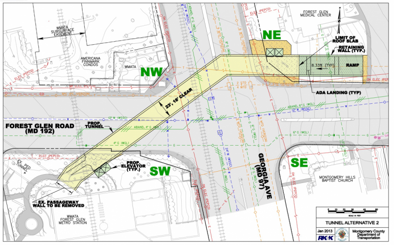
The county is funding a second entrance, diagonally across Georgia and Forest Glen from the primary one.
https://findingforestglen.wordpress.com ... ce-funded/

GGW has a graphic of one version of it.https://ggwash.org/images/made/images/p ... 00_498.png

Conversely, in 2015, GGW was advocating https://ggwash.org/view/38269/a-new-ent ... ghborhoods a second entrance south of the Beltway, near the Traction Power substation https://goo.gl/maps/1xsaeqGkHo62, hidden in a residential neighborhood. This is well south of the platform end, which is inside https://goo.gl/maps/BFe9vnbntR22 the NW cloverleaf of the Beltway-Georgia interchange.

Trivia:
There's also a mid-tunnel vent/evacuation shaft at Seminary and Georgia https://goo.gl/maps/pMUmdWGqLgx; I suspect John will even know the exact distance. Interestingly, there's another Traction Power Station only 1.4 miles north of there, at Windham.https://goo.gl/maps/5kzJ6kWZn662. That strikes me as unusually close.
 #1480974  by Sand Box John
 
The problem with putting a south entrance near the Lansdowne Way substation is two fold. The passage way between the south end of the platforms and the elevator lobby would be 100' greater then the length of the stations 600' long platform. And in order to make said passageway a straight line shot to the platform level elevator lobby, the tunnel would have to pass through and or under the piles that support the western columns and abutment of the Capitol Beltway overpass over Georgia Avenue.

As some know, one of the reasons why the Forest Glen is as deep as it is, is because of the less then desirable stability of the bedrock between the station and the surface. The placement of the two platform arched vaults was dictated by the placement of the columns and abutment mentioned above. The outbound track B1 tunnel is under the southbound roadway of Georgia Avenue, the inbound track B2 tunnel passes under the Capitol Beltway roughly 25' west of the west abutment of the Capitol Beltway overpass. The arched vaults of the station are not parallel to one another, the track centers increase as they approach the Capitol Beltway the decrease on the other side.

The distance between the Lansdowne Way and Windham Lane substations is roughly 7,350', That doesn't include the cable run distance between the substations on the surface and the third rail in the tunnels, Lansdowne Way roughly 240', Windham Lane roughly 160'. The distance between the Lansdowne Way and Silver Spring substations is roughly 7,200' The cable run from the Silver Spring substation to the third rail is roughly 150'.
 #1480979  by farecard
 
Sand Box John wrote:The distance between the Lansdowne Way and Windham Lane substations is roughly 7,350', That doesn't include the cable run distance between the substations on the surface and the third rail in the tunnels, Lansdowne Way roughly 240', Windham Lane roughly 160'. The distance between the Lansdowne Way and Silver Spring substations is roughly 7,200' The cable run from the Silver Spring substation to the third rail is roughly 150'.
I never thought the GGW proposal would fly, based on distance alone, not to mention more mega-dollar elevators. Plus it would double the staffing needs.

I don't know what the optimum spacing for substations is, but I'm seeing passing mentions of every mile. (I don't find figure for how many exist, either. The heat has sapped my Google-fo, I guess. I found mention of upgrading 65 of them.) There is a saga on the Dunn Loring TPS at https://transform66wisely.org/2017/04/2 ... nn-loring/ So what you say makes sense.

BTW, something has changed at the vent shaft north of Wheaton.https://goo.gl/maps/VoUJjXm1NJy The elevators may not have roofs but these exit stairs do.....
 #1480993  by Sand Box John
 
"farecard"

I don't know what the optimum spacing for substations is, but I'm seeing passing mentions of every mile. (I don't find figure for how many exist, either. The heat has sapped my Google-fo, I guess. I found mention of upgrading 65 of them.) There is a saga on the Dunn Loring TPS at https://transform66wisely.org/2017/04/2 ... nn-loring/ So what you say makes sense.


Substation spacing is based on voltage, For WMATA's loads it's close to maximum. Increasing the watts would help but would not effect voltage drop based on Ohm's law. The I-66 article fails to mention the issue of transmission distances for DC compared to AC. Don't have the total number of substation off the top of my head, as I recall pre Silver line opening was 87. Full Silver line will be north of 110.

BTW, something has changed at the vent shaft north of Wheaton.https://goo.gl/maps/VoUJjXm1NJy The elevators may not have roofs but these exit stairs do.....

One of two thing or both are likely happening there, sound abatement and or rain water intrusion protection.
 #1481009  by farecard
 
Sand Box John wrote: Substation spacing is based on voltage, For WMATA's loads it's close to maximum. Increasing the watts would help but would not effect voltage drop based on Ohm's law. The I-66 article fails to mention the issue of transmission distances for DC compared to AC. Don't have the total number of substation off the top of my head, as I recall pre Silver line opening was 87. Full Silver line will be north of 110.
Actually, voltage drop is a function of the current; and the resistance, here the conductor size predominates. AC vs. DC is irrelevant; what matters is that AC is easily transformed up/down while DC is not. In MD, the TPS's are fed at 13.2 KV, in VA double that. (It's a power company choice, not WMATA.) The TPS reduces & rectifies it to get the 750 VDC.

The upgraded stations are 9MW; so that's {gulp} 12,000 Amps at 750 VDC. I seem to recall the tie breaker stations were sized at 20,000 Amps, so that sounds reasonable. (Any load, be it a train or short to ground, would be fed via several TPS's, so the tie-breaker must be rated to interrupt the full available current.)

And that's why you see the multiple large paralleled cables going to the Wee-Z bonds and the third rail;
BTW, something has changed at the vent shaft north of Wheaton.https://goo.gl/maps/VoUJjXm1NJy The elevators may not have roofs but these exit stairs do.....

One of two thing or both are likely happening there, sound abatement and or rain water intrusion protection.
Actually, I suspect it's temporary protection from adjacent construction debris.
 #1481012  by mtuandrew
 
I like this discussion of 750 VDC substations, if we keep it up I’ll split it into a new topic. Generally the rule is about 1 station per mile on a well-supplied system, so WMATA is about right - it wouldn’t surprise me if the capacity is too low for the 7000s though, let alone for 60 mph+ running.
 #1481065  by farecard
 
No grief here on a split.

It's non-trivial at those values to talk conductor size. But here is some SWAGing

https://www.cse-distributors.co.uk/cabl ... able-4e1a/ talks about 1400 amps in 500 mm^2 cable;
that has a diameter of 35.6mm => 1.4" in diameter. That's big; usually no one talks about anything above 4/0 ("four aught" to any EE/electrician) size.

But we need 12,000 Amps; that's 8.5 cables.

But wait....there's a slew of derating factors: cables enclosed in conduit get hotter, cables adjacent to other cables, etc.
And every bit of voltage drop is wasted money/unwanted heat.

Chances are there are several cable bundles to the track. No one has said so, but I'd guess there's a tie-breaker at every power station track connection; so one bundle is "north' of the tie-breaker, the other "south".

A word on the tie-breakers. Like virtually every transit system, the WMATA third rail is DC. That means the all the TPS's outputs can be in parallel, despite being fed from different PoCo's on different grids. This saved WMATA's hide in that circa 1990 blackout in the District; all track power was from suburban TPS's. I remember boarding at a station with open faregates and dim emergency lighting, but the train that pulled in was lit and we went slowly, but got home.

When needed, the tie breakers can be opened, isolating the 2 track sections from each other. That and similar disconnects at the TPS is how WMATA can kill the power on the third rail from here to there, while outside the block everything else is still hot. ROCC can open the TB's/kill the third rail; the Blue Light Special boxes trackside have disconnect controls as well.