• Welded Rail is continuous, or is it?

  • Discussion related to DC area passenger rail services from Northern Virginia to Baltimore, MD. Includes Light Rail and Baltimore Subway.
Discussion related to DC area passenger rail services from Northern Virginia to Baltimore, MD. Includes Light Rail and Baltimore Subway.

Moderators: mtuandrew, therock, Robert Paniagua

  by farecard
 
I have a basic rr signaling question, but since it's about Metro.... I'll ask here.

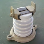
a) The track is split into blocks, isolated from ground [and each other] than each block is paralleled and returned to the substation via the WeeZ bond.

b) WMATA uses welded rail.

There's a contradiction there.

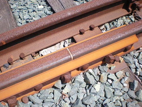
Is the welded rail split and insulated from the next section at each block boundry? If not, how do you delineate Block 1234 from 1235, etc?
  by justalurker66
 
farecard wrote:Is the welded rail split and insulated from the next section at each block boundry?
Yep. Continuous in long segments, not jointed rail which would be clickity clack for more than just where an electrical separation is needed.
Last edited by justalurker66 on Wed Feb 24, 2010 7:54 pm, edited 1 time in total.
  by usa4624
 
Welded rail is the same on Metro and railroads elsewhere. There is no such thing as a continuously welded rail, at least from a manufacture standpoint - it's all forged in 1/4 mile sections (at least in the USA) and then welded together into continuous sections as it is laid down during installation.

Blocks are then cut into it and then filled with plastic 'insulated joints.' These insulated joints are what creates the blocks. Something shunting the rails (or creating a gap) causes the signal system to think the block is occupied.

This is an oversimplification of course, especially for Metro, but it should give you a basic idea of how blocks work.
  by farecard
 
usa4624 wrote:
Blocks are then cut into it and then filled with plastic 'insulated joints.' These insulated joints are what creates the blocks. .
What keeps those joint from making noise/vibration as you cross them?
  by usa4624
 
The cuts for the insulated joints are extremely small and have fillers installed.

I believe Metro uses some type of epoxy /paste to make the surface completely smooth.
  by Sand Box John
 
Allow me to correct some errors in usa4624 post.

The welded rail WMATA uses is composed of multiple pieces 39' long rail, these pieces are welded together to create a length of rail roughly 1,320' long. Where there are sections of track that are that are greater then 1,320', field welds are done.

Insulated joints only exist on either side and within interlockings. There are no insulated joints at track circuit boundaries.

Image
Typical insulated joint

WMATA uses high frequency track circuit as opposed to DC track circuit found on common carrier railroads which eliminating the need for insulated joints at track circuit boundaries. There are 8 frequency used f1 to f8, (2100 Hz to 3900 Hz) f1, f3, f5 an f7 are used on track 1, f2, f4, f6 and f8 are used on track 2. The track circuit have transmitters at one end and a receivers at the other. The impedance bond, also known as WEE-Z_bond, on either end of the track circuit have both a transmitter and receiver in then.

Image
  by farecard
 
Sand Box John wrote: There are no insulated joints at track circuit boundaries.

WMATA uses high frequency track circuit as opposed to DC track circuit found on common carrier railroads which eliminating the need for insulated joints at track circuit boundaries.
So it goes F1a F2a F3a F4a F1b F2b F3b F4b etc.

What prevents a shunt in F2a from also appearing as if F1a & F3a? Also why don't F1a & F1b interfere, if the rail between is continuous? There's some other aspect I don't follow yet. The Xl {reactance} of the tracks at those frequencies is pretty low. I think I need to read up on such somewhere.
  by Sand Box John
 
"farecard"
So it goes F1a F2a F3a F4a F1b F2b F3b F4b etc.


Actually it's f1, f3, f5, f7, f1, f3, f5, f7 etc, the parallel track uses f2, f4, f6, f8, f2, f4, f6, f8 etc

What prevents a shunt in F2a from also appearing as if F1a & F3a?

The track circuit are tuned. The receiver end only hears the frequency transmitted from the other end of the track circuit. It is akin to the sound coming from your car radio when it is tuned to a specific station.

Also why don't F1a & F1b interfere, if the rail between is continuous?

The signal strength from a given transmitter is not strong enough to reach nearby receivers that are tuned to the same frequency.


I will also note, the speed command information is transmitted to the trains using these frequency.
  by usa4624
 
I appreciate the corrections, Sand Box John. I work for a real railroad - WMATA is a bit different.
Sand Box John wrote:Allow me to correct some errors in usa4624 post.
  by farecard
 
usa4624 wrote:I appreciate the corrections, Sand Box John. I work for a real railroad - WMATA is a bit different.
Hey, the Milwaukee was a real railroad; it had to use AC block signaling.
  by Sand Box John
 
"farecard"[/b]

Hey, the Milwaukee was a real railroad; it had to use AC block signaling.


There are different flavors of "AC block signaling". The version WMATA uses is of limited use to common carrier railroads.

High frequency track circuit have limits to their length.